Saturday, October 9, 2010

Other robotics fronts

iRobot Create

A couple weeks ago, iRobot visited the local high school robotics club, where I have been assisting, and donated 6 iRobots create with some additional components, included a command module.


Although I own several *ahem* - a lot of iRobot consumer products, the Create with a command module provides me my robotics fix while I fix my other projects.

So far I have just modified and cleaned up the example programs (which are poorly coded).  Currently it just drives straight until it hits something, and then turns.  Next week I will be teaching the kids in the robotics club how to program for the command module (the green thing) which includes an ATmega168.  Hopefully I will have it chasing down other Creates and ramming them using a little guidance theory, IR rangefinder, and a standard hobby servo.

Look forward to some example code for the command module!

Stellaris (TI) Evalbot

Next, recently TI had a deal where they sold their 'evalbot' for $25! That is $125 dollars off.  I couldn't resist, so I bought one.


Some of the features

The evaluation kit includes the following features:
  • Evaluation board with robotic capabilities
  • Mechanical components assembled by user
  • Stellaris LM3S9B92 microcontroller with 256K Flash, 96K SRAM, USB OTG, Ethernet MAC+PHY, and I2S
  • MicroSD card connector
  • I2S audio codec with speaker
  • USB Host and Device connectors
  • RJ45 Ethernet connector
  • Bright 96 x 16 blue OLED display
  • On-board In-Circuit Debug Interface (ICDI)
  • Battery power (3 AA batteries) or power through USB
  • Wireless communication expansion port
  • Robot features
    • Two DC gear-motors provide drive and steering
    • Opto-sensors detect wheel rotation with 45° resolution
    • Sensors for "bump" detection

Here is a video from TI's website!

It has been a little while, but I am still doing my nerd thing

It has been a bit since my last post, but since the school year has begun and a new season of ANTM has begun, I found myself with some time on my hands.

First off, scavenging around my garage I found a little wooden box that is the perfect size for my power window motors, a scooter battery, and my electronics.  With a little help from a dremel and a coping saw, Boom! One robot chasis.


Things were looking great, until I decided to play with the motors and hooking them straight to the battery to see how fast this thing would move.  Once I had my fun, I plugged it into the high current motor controller and Poof! Instantly I recognized the smell.  Although, it lasted for less than a second, and despite the polarized connector on the board, the battery had been connected with reverse polarity.

Here you can see the damage

Several traces got toasted.  I think the rest of the board may be okay, so perhaps with a little luck and some large globs of solder, my prototype will still work.  Unfortunately, the Xbee I had plugged in at the time seems quite dead.  Amazingly, the Arduino and Xbee shield surviving the incident.

Version 1.1 will include an N-Channel FET for reverse polarity protection, as well as some other minor changes.

I am also working on version 2.0, which will improve on both load capacities and in allowable voltages, as well as add some desired functionality.

Friday, June 25, 2010

Xbee Enabled Joystick, part I

I stalled while working on this project, so I figured if I posted what I have completed so far, I will get the motivation to finish the post.

**Update! I finally got around to doing some more with this, check out Xbee Enabled Joystick, part II**

The Xbee enabled joystick


I had the idea awhile ago, but only recently had a reason to start it.  My work on the high current motor controller left me needing a way to control it remotely.  I've had an old joystick lying around for years, refusing to retire it to the garbage.  I also happened to purchase a couple Xbees a couple years ago, and have never put them to use.

Many people only use Xbee modules as pass through modems, but they can do so much more.  The ZigBee protocol requires a fair amount of overhead, requiring a bit of processing power.  It turns out that Xbee modules let you harness some of the overflow functionality for your own devious doings.  Xbee modules include several ADCs, virtual wires, and more.  Why not hook an Xbee up to an old joystick?

There are a couple of modifications that need to be made to the joystick before you can hook an Xbee up to it.  First off, gaming ports hail from an era where digital I/O was relatively cheap, and good ADCs were expensive.  For a good explanation of how these old joysticks worked, check out this site


The Joystick


Most classic joysticks consist of 2 potentiometers, and several pushbuttons.  More axis were added as joysticks progressed.  The joystick I happen to be modifying has 3 axis, and 4 pushbuttons.

Boy, what a beauty.  How could I throw this away? Every time I pulled it out I was flooded by the nostalgia of staying up late playing Descent with my cheap but sufficient joystick.

The potentiometers in the joystick have one fixed contact connected to the positive rail, and the wiper to the output to the computer's circuitry for reading the position.  In order to use this with an ADC, the other fix contact needs to be connected to ground in order to create a proper voltage divider.

First, opening the joystick
Removing the screws and removing the base reveals this

If you then take off the spring/guide assembly, you can clearly see the pots
If you pull out the PCB and flip it over, with a little probing you can find out what you need to connect to complete your voltage dividers.  For example, here you can see the contacts that this joystick need to be connected
The next step is obviously to solder some wires to the marked contacts.
Now shove the whole thing back together.


The supporting circuitry


Ideally I want this thing to be battery powered and one complete unit with an Xbee poking out of the joystick somewhere, but for now we're going to breadboard it.

First things first, cut that cord
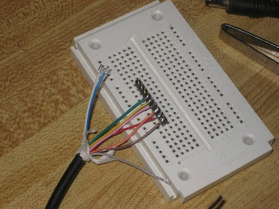
Next, solder (or crimp if you have the luxury) the spliced wires to a .1" pitch header
To supplement the XBee you need a steady voltage supply, and pullup resistors on all of the pushbuttons.  I stole a barrel connector from an old phone to use for power, and then an adjustable voltage regulator to provide the 3.3V the Xbee needs.  Fortunately, nothing in the joystick needs +5V, so we will hook it up to +3.3V.  Here is the completed circuit
 Next up, integrating the Xbee!

Monday, May 3, 2010

Motor Controller + Xbee + Arduino = Awesome


Good news everybody!

The arduino + high current motor controller shield + xbee shield from SparkFun all work together! When I originally designed the motor controller shield a year and a half ago, I had planned on using the original arduino xbee shield. Since then, I discovered the the SparkFun version which features prototyping area, option to switch rx/tx lines to pin2 and pin3, and doesn't require the programming header on the arduino for the reset line.

Although I need to do some more load testing, I couldn't help to throw on some headers and fire it up. All that is left is to add some thermistors for monitoring temperatures, throw the system in an enclosure, and dump it on some wheels and drive it around!

Wednesday, April 28, 2010

High Current Motor Controller Shield Load Test

First off, I got my stackable headers in the mail today. They are Samtec SSQ .1" pitch square tail sockets, with tails about .39" long. I got my headers in 50 pin strips and cut them to size. If that isn't your style you can always buy stackable headers from SparkFun in the 8 pin and the 6 pin variety. Why the stackable headers? An xbee shield is on its way to me as we speak. Here is a pic of the motor controller shield with the stackable headers!

(Note, I also populated the programming header with a double row stacking header to keep compatibility with the original xbee shield)

Next, it's time to put the high current motor controller shield to the test! The plan, hook the shield up to a motor, stall the motor, see how the vnh2sp30's handle the heat, and see if my thermal management was good!


The result? They worked splendidly! When I stopped the motor, it drew 21 amps for an extended duration. The shield got a warm to the touch, but kept on going.

One last note, keep checking back, because the High Current Motor Controller Shield may soon find its way in a store near you!

Wednesday, April 21, 2010

Treaded Platform

I got my hands on a treaded robotics platform the other day. Treaded Platform from RobotShop

This is a perfect platform for testing the high current motor controller shield. More to come, including code and schematics!

Tuesday, April 13, 2010

Tuesday, April 6, 2010

Going gEDA

That's it. I'm transitioning to gEDA from Eagle. Why you might ask? Is it because I am a OSS dork that thinks that anything open source is better? No. Does gEDA have features that make it significantly better than Eagle? No. I like Eagle. There is just one problem. It is expensive.

Eagle provides a great service to hobbyists and students, or anybody non profit by making a free version for non-commercial use. I, however, want to start selling my designs. I probably won't make enough money to justify the truly expensive commercial version of Eagle.

So, long story short, I want to be legit! Expect a comparison of gEDA/PCB and Eagle in a month or so.

Sunday, April 4, 2010

High Current Motor Controller Shield in Action!

A video was promised, here it is!

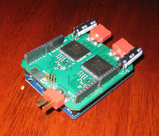
High Current Motor Controller Shield for the Arduino

I've decided what to call it.  It will now be known as the High Current Motor Controller Shield for the Arduino.

Electrical Specifications


Recommended operating conditions:
Voltage input:7-12V
Continuous current output:15A
Peak output current output:30A


Absolute maximum operating conditions:
Voltage input:6-20V
Continuous current output:15A
Peak output current output:30A

Check out the datasheet for the VNH2SP30 for more specific information.

In short, though, the VNH2SP30 has some nice safety features. It features the following safety measures:
  • Undervoltage and overvoltage shut-down
  • Overvoltage clamp
  • Thermal shut down
  • Linear current limiter
  • Cross-conduction protection
  • Protection against loss of ground and loss of
    VCC

The Skinny


Overall, these are very nice resilient chips that are designed for automotive uses. They feature a current sense allowing control loops to try to drive motors with a constant current (also meaning to some extent, constant force).

In the documentation for the VNH2SP30, ST provides ideas for ideas for controlling up to 3 motors with 2 of these chips. Because each chip basically consists of 2 high and low side switches, with separate inputs that force half of the bridge into high impedance, the VNH2SP30 is extremely versatile.

If you do the math, you can safely match the high current motor shield to 2 180W DC motors, or to 1 360W motor! Even better, you can stack these shields to expand capability.

Let me know if anyone is interested in purchasing these items. In larger quantities these could be sold for around $50 to $60 dollars. I originally made these because I could find nothing good that existed between the motor controller shield and the OSMC

Similar Boards


After some digging, I found out that Pololu actually sells something similar to this, and that SparkFun sells a serial enabled version for a little more. The main differences are that they include the reverse voltage protection FETS mentioned in the app note, they have holes instead of pads, and they don't fit nicely on the Arduino. In my experience a big fat pad can be more useful than a hole. For example, I have soldered Dean's Ultra connectors to the pads. Dean's Ultras can handle loads of current, and are polarized, thus helping to protect against reverse voltage.

Regular terminal blocks could be soldered to the pads as pictured.
Hirose DF5 series connectors also work with the shown pads.

Update: A video has been posted here

Wednesday, March 31, 2010

Heavy Duty Arduino Motor Controller

I finally made something!  Amazing!  I personally think it's very cool.


What is it and why should you be excited?  This shield features two of ST Micro's VNH2SP30 Automotive H-bridges.  Each VNH2SP30 can act as a full H-bridge capable of 15 amps continuous with surges up to 30 amps.  You can control 2 large DC motors with this thing.  This is where it gets cooler.  Each VNH2SP30 can act as a half bridge, meaning if you combine these things, you are looking at 30 amps continuous and 60 amps surge!

If that isn't enough for you, you can stack 2 of these on top of each other and create a monster 30 amp 2 motor controller or a beasty 60 amp continuous 120 surge DC motor controller!  Amazing! 

More information to come, including a video of this thing in action! (I just need to charge my batteries)

Saturday, February 13, 2010

How to select Wire and Wire Strippers

Wire strippers are probably the number one tool of any DIY electronics project. Unfortunately, there are a million different types of wire strippers out there. Selecting the right set of wire strippers can be a difficult task. There are also a million different types of wire out there. Which one is right for my project?

Wire

Stranded and Solid Core

There are 2 parts to any wire, insulator and conductor. The conductor in any wire comes in two flavors, stranded and solid core. Solid core wire is as simple as wire can get, a piece of copper or some other conductive metal surrounded by an insulator. Stranded wire consists of many individual 'strands' of smaller diameter conductive material grouped together.

Solid core and stranded wire differ in two different ways. Solid core wire is rigid, and will break if bent multiple times. Stranded wire can be very flexible and is more suitable for applications where there is repetitive deformation. Stranded wire can also carry more current for comparable gauge than solid core.

There is another danger with solid core wire. If stressed, the conductor may break while the insulation stays intact. Visual inspection would show no problem with the wire, yet there would be no conductive path through the wire.

Insulation

Where there are basically on 2 types of conductor, a large number of different types of insulation exist for wire. Gauge refers to only to the size of the conductor, so many variations of the same gauge wire may exist. Some of the more common insulators include:

  • Poly-Vinyl Chloride (PVC)
  • Teflon
  • Silicone
  • Other Plastics

Most standard wires you see are either PVC or a similar material. PVC is non-corrosive, somewhat flexible, impermeable to oil an water, and is suitable for most applications. The other materials serve special purpose. For example, Silicone wires are very flexible and good in rough environments. Teflon coating is usually thin and gives an overall smaller outside diameter.

When selecting parts that connect to wire, such as crimp pins or insulation displacement connectors, pay attention to the maximum (and minimum) outside diameter called for by the part. When wire diameters match what parts ask for, cables or other wire assemblies go together much more smoothly.

Wire Strippers

Matching wire strippers to wire

The most obvious criteria for selecting a wire stripper is wire gauge. Most wire strippers fit into two categories, thin gauge and thick gauge strippers. For example, compare these two sets wire strippers

They are almost identical, except for different hole sizes for the different gauge wire. As a side note, the two sets of wire strippers above are excellent inexpensive general purpose wire strippers, which I obviously recommend.

The Different Styles and Additional Features

A good set of general purpose wire strippers like the ones above will fulfill most people's wire stripping needs. Depending on your needs, however, you might find some of the other styles of wire strippers useful. Here is a rundown of the different type of wire strippers I am familiar with.

Adjustable wire strippers


With 2 sets of 2 blades, this style wire stripper works well with most insulation types. To use these wire strippers, you select the wire gauge with a small wheel near the cutting blades. Then, you select the length of insulation you wish to strip via the small sliding block on the inside of the strippers. You then insert a wire into the end of the strippers until the end hits the block, squeeze both sides (in this case the yellow levers) and pull your wire out, now with a bare end.

Automatic Strippers


If you want a cheap versatile and handy set of wire strippers, get these. The set pictures is designed for coax, but would probably also work for medium gauge wire. These wire strippers automatically close the blades, grip the wire, and pull off the trimmed insulation in a single squeeze. You can get a set of these at your local hardware store for around $25 dollars.


Self Adjusting, Automatic Strippers


These are perhaps my favorite wire strippers. The strippers surprise people when when they see them in action. These strippers automatically adjust for the gauge of the wire. The automatic adjusting can be fine tuned via a sliding mechanism on the top of the strippers. Another useful feature is a sliding adjustable stop for adjusting the length of insulation to be stripped. Not to be outdone by general purpose cheap-o strippers, these also have a wire cutter underneath the stripping mechanism. Using these strippers is as simple as inserting the wire end into the end of the strippers, squeezing, and you're done.

These strippers also have different types of cutting blades, specific for different types of insulation. You can get 2 different cutting blades for it. The general purpose blade

only has 2 separate blades that can strip most wire. As an additional feature, this particular blade can strip multiple wires at the same time. If you need to strip thin insulation, such as Teflon, you need the replacement blade specifically for it, as pictured below.


The major drawback to these wire strippers is price. To get the strippers and the extra blade, you are looking at spending around $100.

Thermal Strippers


Thermal wire strippers cut by melting the insulation down to the conductor. Thermal strippers are clunky, take time to heat up, have a cord, and cost a lot. They don't work with every kind of insulation. Why would you ever want one? Because they will never nick or damage your conductor. The single feature, of a guaranteed perfectly stripped wire, make thermal wire strippers one of the best options for someone that makes a lot of cables, and needs reliability.

Thursday, February 11, 2010

XBee and USB to Serial FTDI latency and dropped packets

You would think that the USB board provided with the XBee dev kit right would work perfectly right out of the box. Unfortunately, you may experience problems depending on your application.

The Problem - Buffering


USB works quite different than RS232, or any serial type communication. A USB client is polled by the host. This means that the client must sit on any data it has until the host asks for it. In a USB to serial converter, the FTDI chip buffers data it receives until either the buffer is full, or until an idle timer triggers the buffer to flush because no data has come on the serial port for a configured amount of time.

The Ugly Side of Buffering


Buffering the data can cause two things to happen. If the data comes in at just the right speed, the buffer will slowly fill, but the timer will not time out. The default timeout for the FTDI driver is 16ms. It takes 62 bytes coming from the serial port to reset the timer. If the FTDI chip receives 62 bytes every 16ms, a timeout will never occur, and the USB block request buffer will slowly fill. The FTDI chip will then only send data out once the USB block request is full. You can figure out the time it will take the buffer to fill with the following equation, given the default block request buffer size is 4096 bytes.

time = 16ms*(size of ftdi buffer)/(62 serial bytes + 2 status bytes)

Worst case,

16ms*4096B/64B = 1.024 seconds

This 4k of data will come in bursts every 1 second. In computing time, this is eternity. Additionally, when the data does come, it comes in bursts of 4kB and at full blast. There is no delay between bytes. If the program or hardware receiving the data from the FTDI over the virtual serial port doesn't service the data fast enough, data will be lost and packets dropped.

The Dropped Packet Solution - Flow Control


To solve the problem of lost data, use flow control. Flow control might not be required on a physical RS232 interface with the same throughput and delays, but on the virtual port it is almost requisite. Enabling flow control is a simple thing to do, especially on the USB board that comes with the XBee dev kit. Any device connected to the FTDI chip should use flow control of some sort.

The Latency Solutions - Block Request Size and Latency Timer


There are 2 ways to fix the latency issues. Fist, you can change the block request size from 4kB down to a smaller value. The second method is to decrease the latency timer value from 16ms to a smaller value. According to FTDI, the preferred method is to change the block request size. In reality a balance of the two methods will yield the best performance per application.

To change the block request size and latency timer settings in windows, open the device manager. In the device manager, find the virtual serial port under 'Ports'. Open up the properties. Under 'Advanced' options on the 'Port Settings' tab, you can change both block request size and latency timer settings.

More information can be found here.