**Update! I finally got around to doing some more with this, check out Xbee Enabled Joystick, part II**
The Xbee enabled joystick
I had the idea awhile ago, but only recently had a reason to start it. My work on the high current motor controller left me needing a way to control it remotely. I've had an old joystick lying around for years, refusing to retire it to the garbage. I also happened to purchase a couple Xbees a couple years ago, and have never put them to use.
Many people only use Xbee modules as pass through modems, but they can do so much more. The ZigBee protocol requires a fair amount of overhead, requiring a bit of processing power. It turns out that Xbee modules let you harness some of the overflow functionality for your own devious doings. Xbee modules include several ADCs, virtual wires, and more. Why not hook an Xbee up to an old joystick?
There are a couple of modifications that need to be made to the joystick before you can hook an Xbee up to it. First off, gaming ports hail from an era where digital I/O was relatively cheap, and good ADCs were expensive. For a good explanation of how these old joysticks worked, check out this site
The Joystick
Most classic joysticks consist of 2 potentiometers, and several pushbuttons. More axis were added as joysticks progressed. The joystick I happen to be modifying has 3 axis, and 4 pushbuttons.
Boy, what a beauty. How could I throw this away? Every time I pulled it out I was flooded by the nostalgia of staying up late playing Descent with my cheap but sufficient joystick.
The potentiometers in the joystick have one fixed contact connected to the positive rail, and the wiper to the output to the computer's circuitry for reading the position. In order to use this with an ADC, the other fix contact needs to be connected to ground in order to create a proper voltage divider.
First, opening the joystick
Removing the screws and removing the base reveals this
If you then take off the spring/guide assembly, you can clearly see the pots
If you pull out the PCB and flip it over, with a little probing you can find out what you need to connect to complete your voltage dividers. For example, here you can see the contacts that this joystick need to be connected
The next step is obviously to solder some wires to the marked contacts.
Now shove the whole thing back together.
The supporting circuitry
Ideally I want this thing to be battery powered and one complete unit with an Xbee poking out of the joystick somewhere, but for now we're going to breadboard it.
First things first, cut that cord
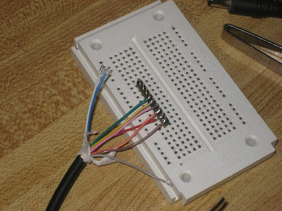
Next, solder (or crimp if you have the luxury) the spliced wires to a .1" pitch header
To supplement the XBee you need a steady voltage supply, and pullup resistors on all of the pushbuttons. I stole a barrel connector from an old phone to use for power, and then an adjustable voltage regulator to provide the 3.3V the Xbee needs. Fortunately, nothing in the joystick needs +5V, so we will hook it up to +3.3V. Here is the completed circuit
Next up, integrating the Xbee!


